10.4.1 Programmable Interrupt Controllers and External Interrupts
Most embedded designs have more than one source of external interrupts, and these multiple external interrupt sources are prioritized. To understand how this process is handled, a clear understanding of the concept of a programmable interrupt controller (PIC) is required.
The PIC is implementation-dependent. It can appear in a variety of forms and is sometimes given different names, however, all serve the same purpose and provide two main functionalities:
· Prioritizing multiple interrupt sources so that at any time the highest priority interrupt is presented to the core CPU for processing.
· Offloading the core CPU with the processing required to determine an interrupt's exact source.
The PIC has a set of interrupt request lines. An external source generates interrupts by asserting a physical signal on the interrupt request line. Each interrupt request line has a priority assigned to it. Figure 10.1 illustrates a PIC used in conjunction with four interrupt sources. Each interrupt source connects to one distinct interrupt request line: the airbag deployment sensor, the break deployment sensor, the fuel-level sensor detecting the amount of gasoline in the system, and a real-time clock.
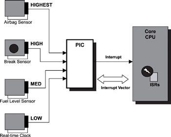
Figure 10.1: Programmable interrupt controller.
Figure 10.1 translates into an interrupt table that captures this information more concisely. The interrupt table lists all available interrupts in the embedded system. In addition, several other properties help define the dynamic characteristics of the interrupt source. Table 10.1 is an example of an interrupt table for the hypothetical example shown in Figure 10.1. The information in the table illustrates all of the sources of external interrupts that the embedded system must handle.
Why is it important to know this information? Understanding the priorities of the interrupt sources enables the embedded systems programmer to better understand the concept of nested interrupts. The term refers to the ability of a higher priority interrupt source to preempt the processing of a lower priority interrupt. It is easy to see how low-priority interrupt sources are affected by higher priority interrupts and their execution times and frequency if this interrupt table is ordered by overall system priority. This information aids the embedded systems programmer in designing and implementing better ISRs that allow for nested interrupts.
The maximum frequency column of the interrupt table specifies the process time constraint placed on all ISRs that have the smallest impact on the overall system.
Table 10.1: Interrupt table.
| Source | Priority | Vector Address | IRQ | Max Freq. | Description |
|---|---|---|---|---|---|
| Airbag Sensor | Highest | 14h | 8 | N/A | Deploys airbag |
| Break Sensor | High | 18h | 7 | N/A | Deploys the breaking system |
| Fuel Level Sensor | Med | 1Bh | 6 | 20Hz | Detects the level of gasoline |
| Real-Time Clock | Low | 1Dh | 5 | 100Hz | Clock runs at 10ms ticks |
The vector address column specifies where in memory the ISR must be installed. The processor automatically fetches the instruction from one of these known addresses based on the interrupt number, which is specified in the IRQ column. This instruction begins the interrupt-specific service routine. In this example, the interrupt table contains a vector address column, but these values are dependent on processor and hardware design. In some designs, a column of indexes is applied to a formula used to calculate an actual vector address. In other designs, the processor uses a more complex formulation to obtain a vector address before fetching the instructions. Consult the hardware manual for specific details. Later sections of this chapter discuss the interrupt service routine in detail. In general, the vector table also covers the service routines for synchronous exceptions. The service routines are also called vectors in short.